Building Envelope/Geomtery - Frequently Asked Questions (FAQ)
Click here to return to main FAQ page
Q: My project is an infill project, and the side walls will be adjacent to the existing walls of neighboring buildings. This will result in little or no heat transfer through these walls. Can I model them as adiabatic interior walls?
A: No. Rules in the ACM specify that shading effects from neighboring buildings are not to be included in compliance models. Extending the logic, the CEC has directed that adjacent buildings are not to be considered in compliance analysis, so the side walls of your building must be modeled as normal exterior walls.
A: No. Rules in the ACM specify that shading effects from neighboring buildings are not to be included in compliance models. Extending the logic, the CEC has directed that adjacent buildings are not to be considered in compliance analysis, so the side walls of your building must be modeled as normal exterior walls.
Q: I don�t like the requirements to import 3-D geometry into CBECC-Com. What alternatives do I have for this purpose?
A: The 2013 Standards have new requirements for mandatory and prescriptive daylit areas and daylighting controls. The only way to correctly calculate the specific building requirements for daylighting is to use Detailed Geometry Method (3D geometry). The Energy Commission does not have the extensive resources that it would require to build a comprehensive user interface to describe 3D building geometry. Instead, we are leveraging other open source software solutions to translate 3D geometry into CBECC-Com. We have demonstrated that this approach works during the first training session on November 19, 2013. Relevant training materials will be made available through our Training/FAQ section at the software download site.
Alternatively if you do not want to use the Detailed Geometry Method, CBECC-Com allows you to model your project using the Simplified Geometry Method. The Simplified Geometry option within CBECC-Com graphical user interface (GUI) allows users to create a building model without specifying coordinates in space for building surfaces such as walls, roofs, and fenestration. The GUI allows a user to create building objects (surfaces) and their child objects by defining the characteristics that define that object without having to use any drawing tools such as SketchUp (with the OpenStudio plug-in). The inputs to define the building envelope components require the user to have detailed take-offs from the construction drawings for each of those components
Q: Are are any limitations to the Simplified Geometry approach?
A: Yes, Simplified Geometry method does not have capability to model impacts of daylighting and shading devices. Note: Capability to model shading devices will be included for Simplified Geometry in CBECC-Com v3b and later.
A: Yes, Simplified Geometry method does not have capability to model impacts of daylighting and shading devices. Note: Capability to model shading devices will be included for Simplified Geometry in CBECC-Com v3b and later.
Q: When I model a building using Simplified Geometry, what building surfaces do I need to include?
A: When developing a mode using the Simplified Geometry approach, the following requirements and recommendations for creating a valid model should be kept in mind:
A: When developing a mode using the Simplified Geometry approach, the following requirements and recommendations for creating a valid model should be kept in mind:
- All exterior surfaces must be modeled
- All interior surfaces separating conditioned from unconditioned spaces must be modeled
- Floors must be modeled for all spaces, including floors between conditioned spaces
- If surfaces between spaces are included, the translation will create the corresponding surface in the adjacent space
- It is not necessary to include interior walls between conditioned spaces, but it is allowed and the additional thermal mass may affect model results
Q: What options are available for importing geometry from other tools? Can I import a Revit model? Can I import gbXML? What if I have an exisiting EnergyPlus idf file?
A: OpenStudio will import gbXML files, which can then be exported as SDD XML for use in CBECC. EnergyPlus idf files can similarly be imorted to OpenStudio for export as SDD files. Revit can export gbXML files, but the Revit model must be carefully developed for use in an energy model. gbXML files exported from Revit often have numerous problems which makes their use problematic.
A: OpenStudio will import gbXML files, which can then be exported as SDD XML for use in CBECC. EnergyPlus idf files can similarly be imorted to OpenStudio for export as SDD files. Revit can export gbXML files, but the Revit model must be carefully developed for use in an energy model. gbXML files exported from Revit often have numerous problems which makes their use problematic.
Q: How do I specify at grade surfaces and below grade surfaces in the Open Studio Plugin?
A: If the project has below grade surfaces that form a basement or at grade surfaces that form a slab, the following steps should be taken in the Open Studio Plugin to prepare the model for CBECC-Com:
A: If the project has below grade surfaces that form a basement or at grade surfaces that form a slab, the following steps should be taken in the Open Studio Plugin to prepare the model for CBECC-Com:
- In OpenStudio using the Inspector tool, under Constructions, create a new CfactorUndergroundWall and/or a new FfactorGroundFloor (there is no need to fill in the Construction details for these because they will need to be entered into CBECC-Com later)
- Double click on the model / space that has the below/at grade surfaces
- Select one of the below grade or at grade surfaces
- In the Inspector tool the OS:Surface dialogue box for the surface you have selected will come up on the right panel
- Set the Outside Boundary Condition to Ground, Sun Exposure to NoSun, Wind Exposure to NoWind, and assign the appropriate Cfactor or Ffactor construction that you just created to the the surface's Construction Name
- Repeat steps 3-6 for the remaining below / at grade surfaces.
Q: Right now any floor in a building can have a multiplier. This does not seem accurate if you can have a roof level with a multiplier or a ground level with a multiplier.
A: As with any building energy simulation tool, it is up to the modeler to provide an accurate representation of the modeled building.
A: As with any building energy simulation tool, it is up to the modeler to provide an accurate representation of the modeled building.
Q: The material library does not include an insulation layer with the R-value of my insulation. How do I model the designed wall?
A: You can use combinations of insulation from the material library that add up to the desired R-value.
A: You can use combinations of insulation from the material library that add up to the desired R-value.
Q: What if a material being used in my design is not listed in the CEC/CBECC-Com material library?
A: You will need to select a material from the library with similar thermal properties to the material being used. You can find the material library in spreadsheet form as part of the CBECC-Com installation in the ...\CBECC-Com 2013 Data\Documents\RulesetSource\CEC 2013 Nonres\Rules\Tables folder of your computer. On a typical installion of CBECC-Com this folder is located in C:\Users\(your username)\Documents\
A: You will need to select a material from the library with similar thermal properties to the material being used. You can find the material library in spreadsheet form as part of the CBECC-Com installation in the ...\CBECC-Com 2013 Data\Documents\RulesetSource\CEC 2013 Nonres\Rules\Tables folder of your computer. On a typical installion of CBECC-Com this folder is located in C:\Users\(your username)\Documents\
Q: How do I model a glazed door?
A: If your door is more than 50% glass, it is considered a glazed door. A glazed door should be represented as a window. If your project uses the Detailed Geometry method, the door can be defined as a Glazed Door in openstudio. For this, create your door then select it, right click and then click Openstudio > SubSurfaceType> Glazed Door as subsurface type as shown in the image. In CBECC-Com this door will appear as a window. Choose Glazed Door as the fenestration construction type while assigning fenestration construction as shown in the image.
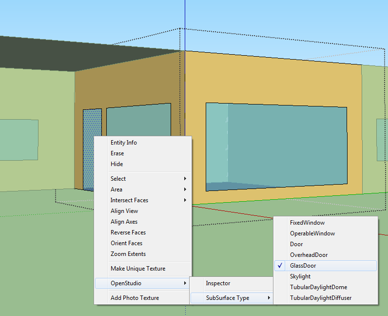
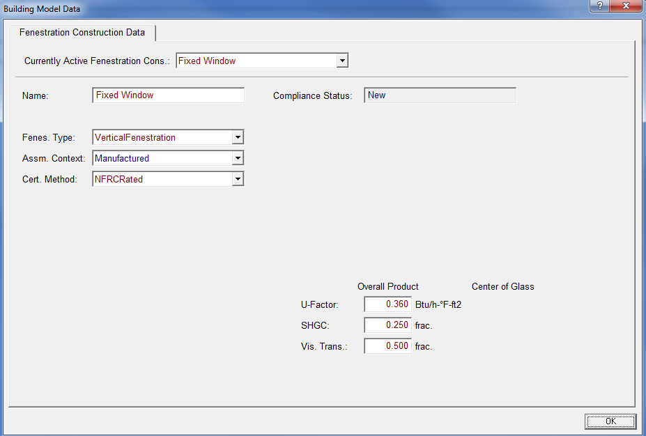
A: If your door is more than 50% glass, it is considered a glazed door. A glazed door should be represented as a window. If your project uses the Detailed Geometry method, the door can be defined as a Glazed Door in openstudio. For this, create your door then select it, right click and then click Openstudio > SubSurfaceType> Glazed Door as subsurface type as shown in the image. In CBECC-Com this door will appear as a window. Choose Glazed Door as the fenestration construction type while assigning fenestration construction as shown in the image.
Q: How can I adjust window areas or window-wall-ratio (WWR) in CBECC-Com?
A: If your project uses Simplified Geometry method, you can change your window areas by editing them directly in the interface. If your project uses Detailed Geometry method, then you can edit the coordinates that define your window by clicking on Surface Geometry button in the Window Data tab
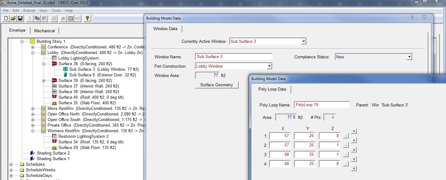
A: If your project uses Simplified Geometry method, you can change your window areas by editing them directly in the interface. If your project uses Detailed Geometry method, then you can edit the coordinates that define your window by clicking on Surface Geometry button in the Window Data tab
Q: Is it possible to increase the height of the spaces in my project within the CBECC-Com interface?
A: If your project uses Simplified Geometry method, you can change the wall areas by editing them directly in the interface. If your project uses Detailed Geometry method, then you can edit the coordinates that define your walls by clicking on Surface Geometry button in the Exterior and Interior Wall Data tabs.
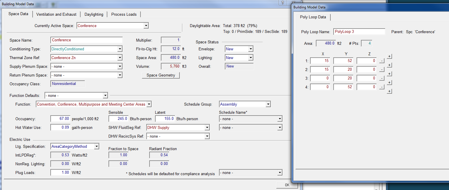
A: If your project uses Simplified Geometry method, you can change the wall areas by editing them directly in the interface. If your project uses Detailed Geometry method, then you can edit the coordinates that define your walls by clicking on Surface Geometry button in the Exterior and Interior Wall Data tabs.
Q: When should I specify Interior Walls when using the Simplified Geometry method?
A: Interior Walls separating two thermally unique spaces should be specified in your Simplified Geometry project.
A: Interior Walls separating two thermally unique spaces should be specified in your Simplified Geometry project.
Q: What are the limitations of Simplified Geometry mode?
A: Currently, shading devices cannot be included in a Simplified Geometry model and credit cannot be taken for daylighting controls. The ability to include window overhangs and fins will be added to the software by the end of the year. Credit for daylighting cannot be included because the spatial information that is required to accurately calculate daylighting effects is not available with Simplified Geometry.Note: Capability to model shading devices will be included for Simplified Geometry in CBECC-Com v3b and later
A: Currently, shading devices cannot be included in a Simplified Geometry model and credit cannot be taken for daylighting controls. The ability to include window overhangs and fins will be added to the software by the end of the year. Credit for daylighting cannot be included because the spatial information that is required to accurately calculate daylighting effects is not available with Simplified Geometry.Note: Capability to model shading devices will be included for Simplified Geometry in CBECC-Com v3b and later
Q: Will CBECC-Com be able to simulate and generate a compliance report from existing CAD files?
A: If the CAD software being used can generate valid gbXML files, these can be imported by the OpenStudio plugin to Sketchup. The CBECC-Com workflow can then continue as normal. Additional functionality may be available in software from commercial vendors.
A: If the CAD software being used can generate valid gbXML files, these can be imported by the OpenStudio plugin to Sketchup. The CBECC-Com workflow can then continue as normal. Additional functionality may be available in software from commercial vendors.
Q: Is it possible to model a non-convex space using only one thermal zone?
A: A so-called �non-convex� space or zone is one where one or more surfaces cannot �see� one or more of the other surfaces in the space or zone. A common example would be an �L� shaped zone. If EnergyPlus is run with �Solar Distribution� set to FullInteriorAndExterior, a zone like this will create errors. However, CBECC-Com runs the EnergyPlus models with Solar Distribution set to FullExterior. In this case, beam solar radiation entering the zone is assumed to fall on the floor, where it is absorbed according to the floor's solar absorptance. Any radiation reflected by the floor is added to the transmitted diffuse radiation, which is assumed to be uniformly distributed on all interior surfaces. Non-convex spaces or zones do not create problems when FullExterior solar distribution is used.
A: A so-called �non-convex� space or zone is one where one or more surfaces cannot �see� one or more of the other surfaces in the space or zone. A common example would be an �L� shaped zone. If EnergyPlus is run with �Solar Distribution� set to FullInteriorAndExterior, a zone like this will create errors. However, CBECC-Com runs the EnergyPlus models with Solar Distribution set to FullExterior. In this case, beam solar radiation entering the zone is assumed to fall on the floor, where it is absorbed according to the floor's solar absorptance. Any radiation reflected by the floor is added to the transmitted diffuse radiation, which is assumed to be uniformly distributed on all interior surfaces. Non-convex spaces or zones do not create problems when FullExterior solar distribution is used.
Q: After working on my model in OpenStudio/Sketchup, I have saved my model and exited Sketchup. When I opened the model up the next day, a number of my building surfaces had disappeared and others were no longer in the correct location. What�s going on and how do I prevent this?
A: When working on a model with the OpenStudio plugin in Sketchup, the model data exist in OpenStudio with the portions being displayed existing in Sketchup as well. Problems can occur if the data in the two programs get out of sync. When a new surface or subsurface is created in Sketchup, OpenStudio makes default assignments to the surface such as the construction type. Since several steps were taken all at once, the undo function is not able revert the model multiple steps to remove the newly created surface. The Sketchup representation will look fine, but no longer matches the underlying OpenStudio data. It is recommended that you never use �Undo� when working on an OpenStudio model in Sketchup.
In addition, the model should always be saved and opened with the OpenStudio plugin by going to the menu Plugins->OpenStudio->File or by using the Open and Save buttons in the OpenStudio toolbar. All model files should end in .osm not .skp. Do not use Sketchup file menu commands when working with OpenStudio Models.
Q: If the undo function in Sketchup can�t be used when working on an OpenStudio model, how do I correct an error I just made?
A: Use the selection tool to select a line segment of the surface that needs to be removed and then use the eraser tool or press the delete key. Then redraw the correct surfaces or subsurfaces.
A: Use the selection tool to select a line segment of the surface that needs to be removed and then use the eraser tool or press the delete key. Then redraw the correct surfaces or subsurfaces.
Q: Even though I haven�t used Undo when working on my OpenStudio model, when I reopened the model I found errors similar to what are described as being caused by Undo. What else can I do?
A: File corruption can still occur. A good practice is to frequently save the model (Plugins>OpenStudio>File>Save). Also, corruption can affect the current working file, even if it is not explicitly saved. A useful practice to ensure that your most recently saved file is uncorrupted is to save as described above, but then immediately save again, but using Save As, to a new file name. Then if the working file is corrupted, the previously saved file with the original name is unaffected.
A: File corruption can still occur. A good practice is to frequently save the model (Plugins>OpenStudio>File>Save). Also, corruption can affect the current working file, even if it is not explicitly saved. A useful practice to ensure that your most recently saved file is uncorrupted is to save as described above, but then immediately save again, but using Save As, to a new file name. Then if the working file is corrupted, the previously saved file with the original name is unaffected.
Q: How can I verify that the geometry of the building I created with SketchUp is not corrupted before importing it into CBECC-Com?
A: It is good practice to periodically close Sketchup and then reopen it and reload your OpenStudio model (.osm). The visual rendering can be used to verify that the desired surfaces and fenestrations are in the model correctly before exporting the SDD XML for use in CBECC-Com.
A: It is good practice to periodically close Sketchup and then reopen it and reload your OpenStudio model (.osm). The visual rendering can be used to verify that the desired surfaces and fenestrations are in the model correctly before exporting the SDD XML for use in CBECC-Com.
Q: What is the difference between adding window shades in a detailed geometry model and a simplified geometry model?
A: Window shades can be added to individual windows within the CBECC-Com interface in version 3b and above. In detailed geometry, the shade will interact with all surfaces that the shade casts a shadow on. In simplified geometry, the shade only interacts with the surface that the window shade is attached to and any of its sub-surfaces. Since daylighting is not modeled for simplified geometry models, adding shades will have no impact on daylighting. In detailed geometry models, adding shades will affect daylighting of spaces where shades are added.
A: Window shades can be added to individual windows within the CBECC-Com interface in version 3b and above. In detailed geometry, the shade will interact with all surfaces that the shade casts a shadow on. In simplified geometry, the shade only interacts with the surface that the window shade is attached to and any of its sub-surfaces. Since daylighting is not modeled for simplified geometry models, adding shades will have no impact on daylighting. In detailed geometry models, adding shades will affect daylighting of spaces where shades are added.
Click here to return to main FAQ page